Home / Projects / PRJ-07 Interceptor
Interception Robot
OBJECT DETECTION · KALMAN ESTIMATION · PID ACTUATION · ARTIFACTS UNAVAILABLE
A portfolio account of a Raspberry Pi-class perception-to-actuation prototype: detect a target, estimate its motion, and drive bounded commands. Sub-100 ms operation is a reported prototype result; the source, raw timing traces, and hardware media are not currently available for public review.
00Evidence status
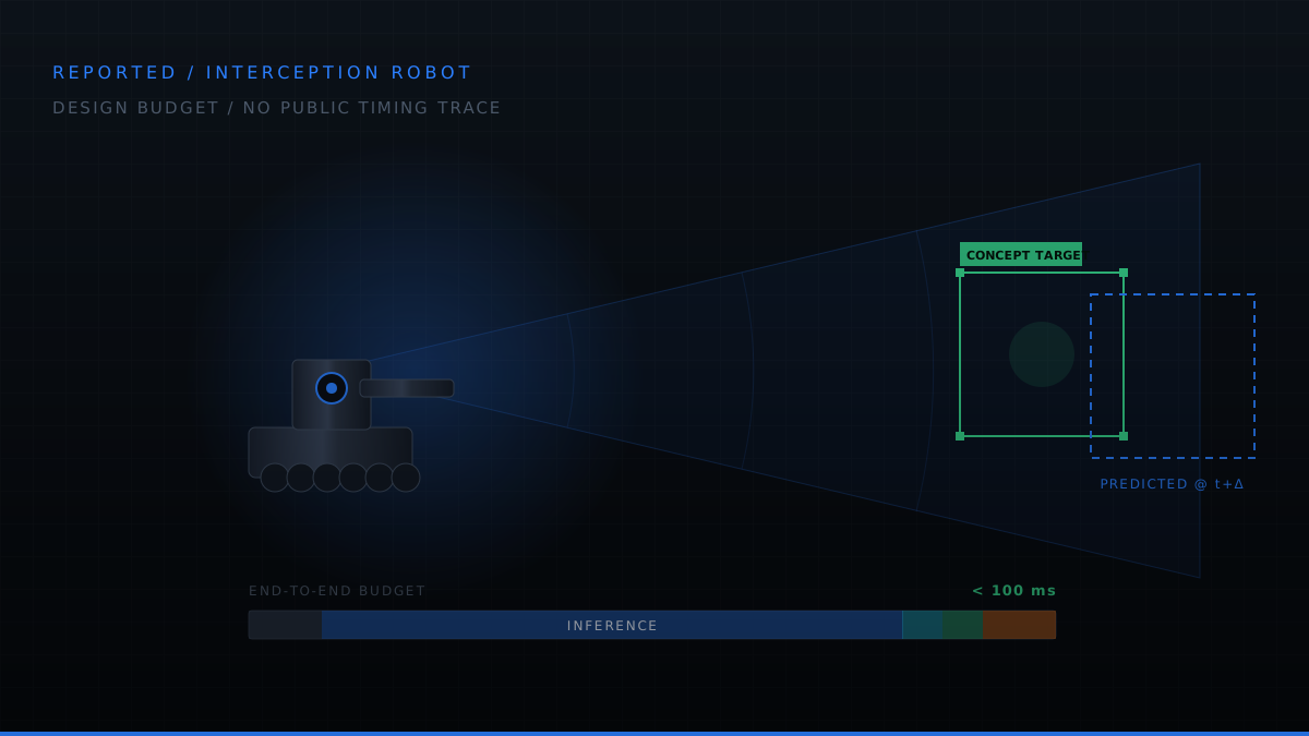
Portfolio claim: the prototype reportedly integrated object detection, Kalman filtering, and PID actuation on Raspberry Pi 4-class hardware, with a reported end-to-end latency below 100 ms.
Review boundary: no discoverable repository, test log, timing histogram, result plot, hardware photograph, or technical report was available during this portfolio audit. The architecture discussion is retained, while performance figures are explicitly labeled as reported rather than independently reproducible.
Evidence source: project narrative supplied for this portfolio. Public verification artifacts are unavailable.
Build the latency budget
Set each stage of the perception-to-actuation pipeline and watch the total against the 100 ms design target, then see the angular lag that budget produces and what predicting across the delay recovers.
This model needs JavaScript. Everything it demonstrates is described in the sections below.
01Problem
A tracking system that reacts to where the target was will always trail it. Every millisecond between photon and motor command becomes an angular lag that scales with target speed, and a neural detector on a CPU-only embedded board is slow enough that the lag dominates the error budget.
The proposed architecture addresses that lag in two ways: shorten the loop, and predict across the measured delay that remains. A stage-by-stage latency budget makes the bottleneck visible, while a Kalman filter can propagate the estimate to the expected moment of actuation.
Design target. Close a perception-to-actuation loop on Raspberry Pi-class hardware under a 100 ms end-to-end budget, then preserve the instrumented evidence needed to show that the target was met across more than one favorable run.
01ADesign requirements
These are the reported prototype requirements. The intended verification method is shown, but the corresponding public test artifacts are not available.
| ID | Requirement | Target | Intended verification |
|---|---|---|---|
| IN-001 | End-to-end closed-loop latency shall be bounded | < 100 ms | Instrumented timing |
| IN-002 | Target shall be detected from a live camera stream | YOLO detector | Detection run |
| IN-003 | Target state shall be estimated, not merely detected | Kalman filter | Track continuity test |
| IN-004 | Track shall survive missed detections | Predict-only coast | Dropout injection |
| IN-005 | Control output shall be smooth and bounded | PID + limits | Command trace |
| IN-006 | System shall run entirely on the embedded target | Raspberry Pi 4, CPU only | Hardware run |
| IN-007 | Per-stage latency shall be measurable | Instrumented | Profiling output |
01BReported constraints
- CPU-only inference. No GPU, no NPU, no accelerator, the detector runs on the same four cores as everything else.
- Single camera at fixed frame rate; the detector cannot run faster than frames arrive.
- PWM-driven motors with finite slew rate and mechanical inertia.
- Shared OS. Linux is not a real-time kernel, so scheduling jitter is part of the budget.
- Latency is a requirement, not an outcome. Every stage gets an allocation and is measured against it.
- Detection is unreliable by nature. The system must behave correctly on frames where the detector returns nothing.
- No cloud, no offboard compute. Everything closes on the vehicle.
02Architecture
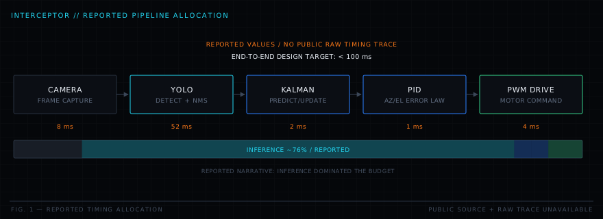
The reported design uses a staged pipeline and a budget per stage. The project narrative identifies inference as roughly three quarters of the total loop time, which would correctly focus optimization on model size, input resolution, and frame scheduling. The underlying timing trace is not public.
Design decisions
| Decision | Chosen | Rejected alternative | Rationale |
|---|---|---|---|
| DD-1 | Kalman filter between detector and controller | Drive the controller from raw detections | Raw detections are noisy, intermittent and already stale; the filter smooths, predicts, and survives dropouts |
| DD-2 | Neural detector | Classical colour/blob tracking | Robust to lighting and background variation that defeats threshold-based tracking |
| DD-3 | Predict to actuation time | Use the estimate at detection time | The estimate is already tens of milliseconds old when it reaches the motors; propagating it forward removes that lag from the error |
| DD-4 | Per-stage instrumentation | Measure end-to-end only | An end-to-end number tells you that you are slow; a per-stage breakdown tells you where |
| DD-5 | Independent azimuth/elevation loops | Coupled MIMO controller | The axes are mechanically near-decoupled, so two simple loops are easier to tune and to reason about |
03Estimation & control design
The equations document the reported estimator and controller structure. They are not a substitute for executable source, tuning files, or test traces.
Target state model
Predict / update
The predict step runs unconditionally. That is what makes a missed detection a graceful degradation , the covariance grows, the estimate coasts, and the controller keeps receiving a valid state instead of a gap.
Latency compensation
Control law
03AReported algorithms
- YOLO single-shot detection with non-maximum suppression to resolve overlapping candidate boxes.
- Linear Kalman filter on a constant-velocity image-plane model, providing smoothing, prediction and dropout tolerance.
- Nearest-neighbour data association gated by predicted position, so a spurious detection elsewhere in the frame cannot capture the track.
- Latency compensation by forward-propagating the state through the measured capture-to-actuation interval.
- PID with anti-windup and output clamping on independent azimuth and elevation axes.
- Per-stage timing instrumentation feeding a live latency breakdown.
04Reported implementation
The stack below is drawn from the project narrative; no public dependency lockfile, source tree, or hardware configuration record is linked.
| Language | Python with OpenCV and NumPy |
|---|---|
| Detection | YOLO object detector, CPU inference |
| Estimation | Linear Kalman filter, constant-velocity model |
| Control | PID on azimuth and elevation, PWM motor drive |
| Platform | Raspberry Pi 4, embedded Linux |
| Instrumentation | Per-stage timestamps with a rolling latency histogram |
05Reported test approach
The portfolio record describes the following checks. Test code, logs, sample counts, acceptance thresholds, and failure records were not available during the audit.
- Filter checks: known-trajectory inputs and prediction-only behavior during withheld detections.
- Detector characterization: detection and false-positive behavior across changing scenes.
- Latency profiling: timestamps at each pipeline boundary rather than only one end-to-end value.
- Closed-loop tracking: moving-target runs with target speed and tracking error recorded together.
06Reported performance
If reproduced, the stage breakdown would be the most decision-useful artifact: it would show whether capture, inference, filtering, control, or actuation dominates the loop. The current portfolio can report the original figures, but cannot show their distribution, run count, or worst-case behavior.
06AReported outcomes
- Reported: sub-100 ms closed-loop latency on Raspberry Pi 4 with CPU-only inference.
- Reported: detection, Kalman estimation, and PWM motor control integrated into one loop.
- Reported: prediction-only operation maintained a command input during missed detections.
- Not publicly demonstrated: timing distribution, tracking-error reduction, or dropout-recovery traces.
No chart is shown because no raw measurement series was available from which to generate one honestly.
07Engineering tradeoffs
| Tradeoff | Gained | Paid |
|---|---|---|
| Neural detector over classical vision | Potential robustness to lighting and background | Reported to consume roughly three quarters of the latency budget |
| Lower input resolution | Faster inference, shorter loop | Reduced detection range and small-target sensitivity |
| Constant-velocity motion model | Cheap, stable, easy to tune | Lags during genuine target acceleration |
| Latency compensation by prediction | Removes systematic tracking lag | Amplifies estimate error during manoeuvres, predicting a wrong velocity forward makes it worse |
| Independent axis controllers | Simple tuning and diagnosis | Ignores whatever cross-axis coupling exists mechanically |
07ADesign challenges
Inference dominating the loop
The project narrative reports that inference dominated the loop. Reproducing this result requires per-stage timestamp logs, device configuration, model identity, input resolution, and enough cycles to expose scheduling tails rather than only an average.
Detection dropouts breaking the loop
A controller driven directly from intermittent detections can stutter or hold stale commands. The reported design places a continuously predicting Kalman filter between perception and control; a public dropout trace is still needed to quantify coast duration and reacquisition behavior.
Scheduling jitter
On a non-real-time kernel, wall-clock time can vary from cycle to cycle. A credible latency claim therefore needs percentile and maximum timing, not just a nominal or mean value.
07BLessons learned
- Measure before optimising. Intuition about where time goes in a perception pipeline is reliably wrong.
- Latency is error. In a tracking loop, delay and inaccuracy are the same quantity expressed in different units.
- Put an estimator between perception and control. It decouples an unreliable, intermittent sensor from a controller that needs a continuous input.
- Compensate with measured time, not assumed time. On a general-purpose OS, nominal timing is a fiction.
- The budget is the design document. Publishing per-stage allocations made every subsequent decision obvious.
08Next evidence gates
- Publish source, locked dependencies, model identity, hardware configuration, and run instructions.
- Publish raw per-stage timestamps with sample count, mean, percentiles, and maximum.
- Publish tracking-error and dropout-recovery traces tied to repeatable test inputs.
- Then evaluate quantized detection, a maneuvering-target model, and tighter scheduling controls.
09Source status
No discoverable public project artifact supports a source or download link here. This replaces the previous empty gallery and report-request placeholders with the actual evidence state.
When source and measurement artifacts are available, this section should link directly to immutable revisions and raw data rather than an availability promise.